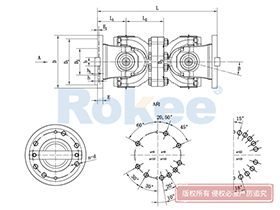
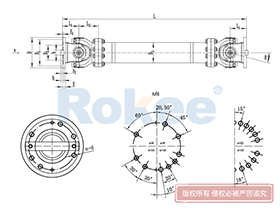
Universal Coupling Joints Assembly Drawing
Rokee® is a well-known high-quality universal coupling joint supplier from china, learn more about universal coupling joints assembly drawing, pls contact Rokee technology. Rokee has been established in China since 1999, over the years, with excellent quality, we have been continuously providing many universal coupling joint products of various categories and uses complying with multiple standards and a full range of services, from the universal coupling joint selection to final installation and operation, for the industry fields of ferrous metallurgy, nuclear power, gas turbine, wind power, ropeway construction, lifting transportation, general equipment, etc.
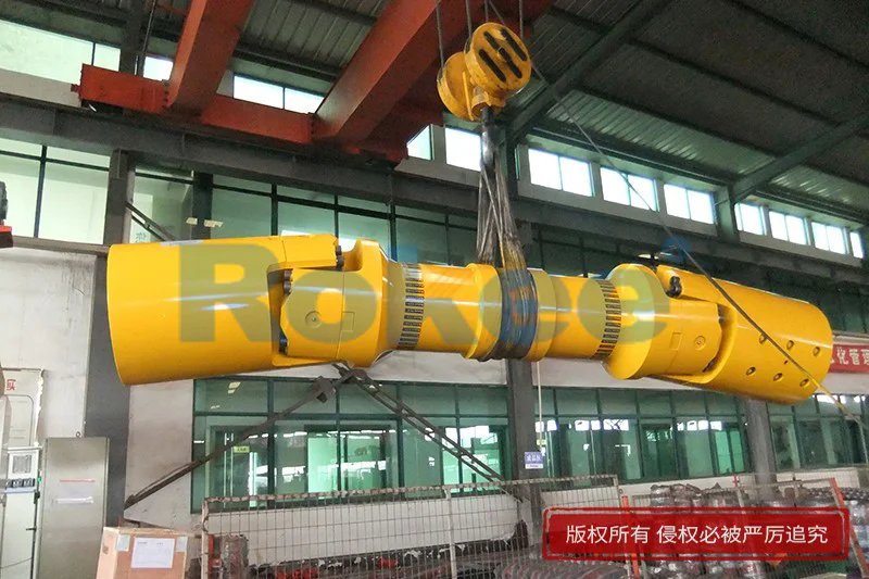


The universal coupling joint uses cross bearings to connect the flanges at both ends, which can transmit torque that is not on the same axis. The diagonal compensation can reach more than 25°, and the spline connection can compensate for the axial displacement in a large distance. With high carrying capacity and excellent transmission efficiency, universal coupling joint is widely used in modern industrial fields.
Universal Coupling Joint Products
-
![ROWS-BH Cardan Shaft,Universal Coupling Joints Assembly Drawing]()
ROWS-BH Cardan Shaft
View More -
![ROWL-BH Cardan Shaft,Universal Coupling Joints Assembly Drawing]()
ROWL-BH Cardan Shaft
View More -
![ROWM-BH Cardan Shaft,Universal Coupling Joints Assembly Drawing]()
ROWM-BH Cardan Shaft
View More -
![ROWH-BH Cardan Shaft,Universal Coupling Joints Assembly Drawing]()
ROWH-BH Cardan Shaft
View More -
![ROWS-WD Cardan Shaft,Universal Coupling Joints Assembly Drawing]()
ROWS-WD Cardan Shaft
View More -
![ROWM-WD Cardan Shaft,Universal Coupling Joints Assembly Drawing]()
ROWM-WD Cardan Shaft
View More -
![ROWH-WD Cardan Shaft,Universal Coupling Joints Assembly Drawing]()
ROWH-WD Cardan Shaft
View More -
![ROWL-WD Cardan Shaft,Universal Coupling Joints Assembly Drawing]()
ROWL-WD Cardan Shaft
View More -
![ROWM-WH Cardan Shaft,Universal Coupling Joints Assembly Drawing]()
ROWM-WH Cardan Shaft
View More -
![ROWH-WH Cardan Shaft,Universal Coupling Joints Assembly Drawing]()
ROWH-WH Cardan Shaft
View More -
![ROWL-WH Cardan Shaft,Universal Coupling Joints Assembly Drawing]()
ROWL-WH Cardan Shaft
View More -
![ROWS-WH Cardan Shaft,Universal Coupling Joints Assembly Drawing]()
ROWS-WH Cardan Shaft
View More -
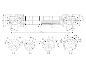
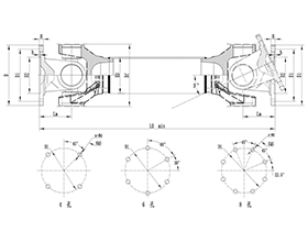
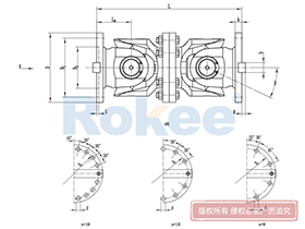
![SWC-BH Universal Coupling,Universal Coupling Joints Assembly Drawing]()
SWC-BH Universal Coupling
standard telescopic welded
View More -
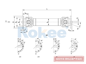
![SWC-CH Uuniversal Coupling,Universal Coupling Joints Assembly Drawing]()
SWC-CH Uuniversal Coupling
Long Telescopic Welded
View More -
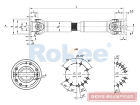
![SWC-DH Universal Coupling,Universal Coupling Joints Assembly Drawing]()
SWC-DH Universal Coupling
Short Telescopic Welded
View More -
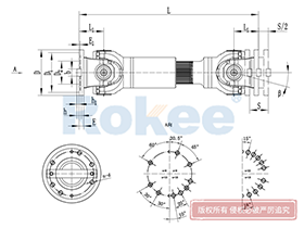
![SWC-WD Universal Coupling,Universal Coupling Joints Assembly Drawing]()
SWC-WD Universal Coupling
Non-telescopic Short
View More -
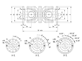
![SWC-WH Universal Coupling,Universal Coupling Joints Assembly Drawing]()
SWC-WH Universal Coupling
Non-telescopic Welded
View More -
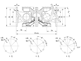
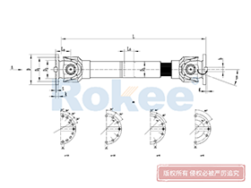
![SWP-A Universal Coupling,Universal Coupling Joints Assembly Drawing]()
SWP-A Universal Coupling
Long Type, Telescopic
View More -
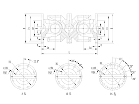
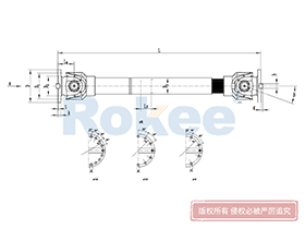
![SWP-B Universal Coupling,Universal Coupling Joints Assembly Drawing]()
SWP-B Universal Coupling
Short Type, Telescopic
View More -
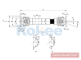
![SWP-C Universal Coupling,Universal Coupling Joints Assembly Drawing]()
SWP-C Universal Coupling
Short Type, Non-telescopic
View More -
![SWP-D Universal Coupling,Universal Coupling Joints Assembly Drawing]()
SWP-D Universal Coupling
Long Type, Non-elescopic
View More

In the realm of mechanical engineering and power transmission systems, universal coupling joints stand as indispensable components, tasked with transferring rotational torque and motion between shafts that are misaligned, intersecting, or subject to dynamic positional shifts during operation. These joints, often referred to as Cardan joints or Hooke’s joints in technical contexts, bridge the gap between non-collinear shafts, enabling smooth power delivery across a wide spectrum of industrial, automotive, and heavy machinery applications. At the heart of ensuring the proper fabrication, assembly, and functional performance of these critical components lies the universal coupling joints assembly drawing—a comprehensive technical document that serves as the ultimate guide for manufacturers, assemblers, maintenance personnel, and design engineers alike. Far more than a mere visual representation, this assembly drawing encapsulates every critical detail of the universal coupling joint’s structure, component relationships, dimensional specifications, assembly sequences, and functional tolerances, laying the groundwork for consistent, reliable, and durable end products that meet operational demands across diverse working environments.
To fully grasp the significance of the universal coupling joints assembly drawing, it is first essential to understand the fundamental composition of a standard universal coupling joint, as this structure directly shapes the content and layout of the drawing. A typical universal coupling joint consists of several core components, each with a distinct role in facilitating torque transmission and accommodating shaft misalignment. The primary structural elements include two yoke assemblies—one attached to the driving shaft and the other to the driven shaft—each featuring a U-shaped frame designed to cradle the central connecting component. This central component is the cross shaft, also known as the spider, a rigid, cross-shaped part that links the two yokes at a 90-degree angle to one another, allowing for angular articulation between the shafts. Complementing these main parts are precision bearings, usually needle roller bearings, fitted onto the four journals of the cross shaft; these bearings minimize friction between the cross shaft and the yokes, enabling smooth rotation and reducing wear during continuous operation. Additional supporting components include bearing caps, retaining rings, seals, and fasteners such as bolts or nuts, which secure the bearings in place, prevent lubricant leakage, and block the ingress of contaminants like dust, moisture, and debris that could compromise the joint’s integrity. Each of these components is meticulously documented on the assembly drawing, with clear delineation of their individual identities, positions, and interconnections to eliminate ambiguity during the assembly process.
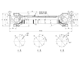
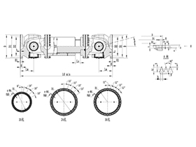
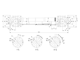
The universal coupling joints assembly drawing adheres to strict international technical drawing standards, ensuring uniformity and readability across global engineering and manufacturing teams. Unlike detailed part drawings that focus on a single component’s geometry and specifications, the assembly drawing adopts a holistic view, illustrating how all individual parts fit together to form a fully functional universal coupling joint. One of the key features of this drawing is the use of orthographic projection, typically presenting front, top, and side views to showcase the joint’s external profile and internal component arrangement from multiple perspectives. In many cases, sectional views are incorporated to reveal the internal mating relationships between the cross shaft, bearings, and yokes, as these hidden interfaces are critical for proper assembly and cannot be fully visualized in standard external views. Each component is labeled with a unique item number, which corresponds to a detailed bill of materials (BOM) included either on the same drawing sheet or as a supplementary document. The BOM lists each part’s description, material specification, quantity required per assembly, and any additional notes related to its manufacturing or treatment, providing a complete inventory that streamlines procurement and production workflows.
Dimensional accuracy is the cornerstone of the universal coupling joints assembly drawing, as even minor deviations in dimensions can lead to assembly failures, poor fit, or premature wear in the finished joint. The drawing specifies all critical dimensions, including overall length and diameter of the assembled joint, bore diameters of the yokes for shaft mounting, distance between bearing seats on the yokes, and the length and diameter of the cross shaft journals. Beyond basic linear dimensions, the drawing also defines essential geometric tolerances that govern the joint’s functional performance, such as parallelism, perpendicularity, concentricity, and angular runout. These tolerances ensure that the cross shaft rotates smoothly within the yokes, that the bearing seats are properly aligned to prevent uneven loading, and that the assembled joint can accommodate the designed range of angular misalignment without binding or generating excessive vibration. Tolerance values are carefully calibrated based on the joint’s intended application—higher precision tolerances are specified for joints used in high-speed, high-torque machinery, while slightly more relaxed tolerances may apply to heavy-duty, low-speed industrial joints, always balancing performance requirements with manufacturing feasibility.
Beyond dimensional and geometric specifications, the universal coupling joints assembly drawing integrates a wealth of technical notes and assembly instructions that guide the entire fabrication and assembly process. These notes cover a wide range of critical considerations, starting with surface finish requirements for key mating surfaces, such as the cross shaft journals and yoke bearing seats, to ensure optimal bearing performance and reduce friction. Lubrication specifications are also clearly outlined, detailing the type of lubricant suitable for the joint’s operating temperature and load conditions, as well as lubrication points and intervals for initial assembly and ongoing maintenance. The drawing may also include notes on heat treatment processes for load-bearing components like the cross shaft and yokes, such as quenching and tempering to enhance hardness and wear resistance, without altering the core structural integrity of the parts. For assembly-specific guidance, the notes may highlight sequential steps for component fitting, such as pressing bearings into the yoke seats, aligning the cross shaft with the yokes, securing retaining rings to prevent axial movement, and torquing fasteners to the specified tension to avoid over-tightening or under-securing. These instructions are designed to minimize human error during assembly, ensuring that every joint is constructed consistently and in accordance with the original design intent.
The assembly process of universal coupling joints, as dictated by the drawing, follows a logical, step-by-step sequence that prioritizes precision and component protection. The first stage involves preparing all individual components, ensuring that each part is free from burrs, machining debris, or surface defects that could interfere with fit or cause damage during assembly. Bearing seats in the yokes are cleaned thoroughly, and any protective coatings are removed from mating surfaces to promote proper adhesion and load distribution. Next, the needle roller bearings are fitted onto the cross shaft journals; this process requires careful alignment to avoid damaging the bearing rollers or the journal surfaces, often using specialized pressing tools to apply uniform pressure and ensure the bearings are seated flush against the cross shaft shoulders. Once the bearings are in place, the cross shaft assembly is positioned between the two yokes, with each bearing set nested into the corresponding bearing seats on the yoke frames. Alignment is critical at this stage, as the yokes must be positioned at a precise 90-degree angle relative to one another to enable the joint’s angular flexibility. Retaining rings or bearing caps are then installed to lock the bearings in place, preventing axial displacement during rotation, and fasteners are tightened in a staggered, incremental pattern to distribute clamping force evenly and avoid warping the yoke structures.
After the initial assembly, the drawing guides technicians through a series of inspection and verification steps to confirm the joint’s quality and functionality. A visual inspection is conducted to check for proper component alignment, secure fastening, and intact seals, ensuring no parts are misaligned or missing. Functional testing follows, where the joint is manually rotated through its full range of designed angular misalignment to check for smooth operation, binding, or excessive play. Any signs of stiffness or uneven rotation indicate a dimensional discrepancy or assembly error, which is addressed by referencing the drawing’s specifications to identify and correct the issue. This inspection phase is vital, as it catches defects early in the production process, preventing faulty joints from entering service and avoiding costly downtime or equipment damage in operational settings. The assembly drawing serves as the reference standard for all inspections, with inspectors cross-referencing every dimension, tolerance, and component position against the drawing to validate compliance.
The versatility of universal coupling joints is reflected in the adaptability of their assembly drawings, which are customized to suit different design variations and application requirements. Single universal joints, which accommodate angular misalignment between intersecting shafts, have a simplified assembly drawing compared to double universal joints, which feature two interconnected single joints and a intermediate shaft to handle parallel misalignment or larger angular offsets. Similarly, assembly drawings for heavy-duty industrial joints used in mining, construction, or agricultural machinery include additional reinforcement details, such as thicker yoke walls, larger cross shafts, and heavy-duty bearings, with corresponding adjustments to dimensions and tolerances to handle higher torque loads and harsh operating conditions. For joints integrated into automotive drive systems, the assembly drawing prioritizes compactness, lightweight materials, and high-speed performance, with specifications tailored to the dynamic vibrations and rotational speeds typical of vehicle operation. Regardless of the design variation, the core purpose of the assembly drawing remains consistent: to translate conceptual design into a tangible, manufacturable product that meets the unique demands of its intended application.
In the modern engineering landscape, the role of the universal coupling joints assembly drawing has evolved alongside advances in computer-aided design (CAD) technology, shifting from traditional hand-drafted blueprints to digital 2D and 3D assembly models. Digital assembly drawings offer enhanced clarity and functionality, allowing engineers to create fully interactive 3D representations of the universal coupling joint, where components can be rotated, disassembled, and examined in virtual space to identify potential assembly conflicts or design flaws before physical production begins. These digital files can be easily shared across global teams, integrated with computer-aided manufacturing (CAM) systems for automated production, and archived for future reference or design modifications. Despite this digital transformation, the fundamental content and purpose of the assembly drawing remain unchanged—it still serves as the definitive source of technical information, bridging the gap between design conceptualization and real-world execution. Even with the efficiency of digital tools, the precision and comprehensiveness of the assembly drawing remain non-negotiable, as it continues to be the primary document that ensures consistency, quality, and compliance across every stage of the product lifecycle.
Long-term performance and maintenance of universal coupling joints are also deeply tied to the information presented in the assembly drawing. For maintenance teams, the drawing provides a clear roadmap for disassembling, inspecting, and repairing joints in service, helping to identify worn components such as bearings or seals, understand the correct disassembly sequence to avoid component damage, and reassemble the joint to original specifications. The drawing’s material and lubrication notes guide maintenance personnel in selecting replacement parts and lubricants that match the original design, ensuring compatibility and extending the joint’s service life. In cases where modifications or upgrades are needed, engineers rely on the assembly drawing to assess the existing design, evaluate the impact of changes, and update specifications accordingly, ensuring that any alterations maintain the joint’s structural integrity and functional capabilities. This ongoing utility makes the assembly drawing a living document, relevant not only during production but throughout the entire operational lifespan of the universal coupling joint.
Looking ahead, the importance of universal coupling joints assembly drawings will only continue to grow as mechanical systems become more complex, with demands for higher efficiency, greater durability, and tighter dimensional precision driving advancements in joint design. As industries push for more sustainable and reliable power transmission solutions, the assembly drawing will remain a critical tool for optimizing design, streamlining manufacturing, and ensuring that universal coupling joints can meet the evolving challenges of modern machinery. Whether in traditional industrial settings, cutting-edge automotive systems, or emerging heavy equipment applications, the assembly drawing stands as a testament to the precision and discipline of mechanical engineering, turning abstract design principles into tangible components that keep the world’s machinery moving. Every line, dimension, and note on the drawing plays a vital role in this process, underscoring why this technical document is irreplaceable in the development, production, and maintenance of universal coupling joints.
In summary, the universal coupling joints assembly drawing is far more than a technical schematic—it is the backbone of successful universal coupling joint production and operation. It consolidates design intent, manufacturing requirements, and functional specifications into a single, accessible document, guiding every step from component fabrication to final assembly, inspection, and long-term maintenance. By defining component relationships, dimensional tolerances, assembly sequences, and performance standards, the drawing ensures that each universal coupling joint is built to perform reliably, withstand operational stresses, and deliver consistent power transmission across diverse applications. In an industry where precision and reliability are paramount, the universal coupling joints assembly drawing remains an essential asset, embodying the meticulous engineering that drives efficiency and durability in mechanical power transmission systems.
« Universal Coupling Joints Assembly Drawing » Update Date: 2026/3/7
URL: http:/en/blog/universal-coupling-joints-assembly-drawing.html