Universal Couplings Size Chart
Rokee® is a well-known high-quality universal coupling supplier from china, learn more about universal couplings size chart, pls contact Rokee technology. Rokee has been established in China since 1999, over the years, with excellent quality, we have been continuously providing many universal coupling products of various categories and uses complying with multiple standards and a full range of services, from the universal coupling selection to final installation and operation, for the industry fields of ferrous metallurgy, nuclear power, gas turbine, wind power, ropeway construction, lifting transportation, general equipment, etc.
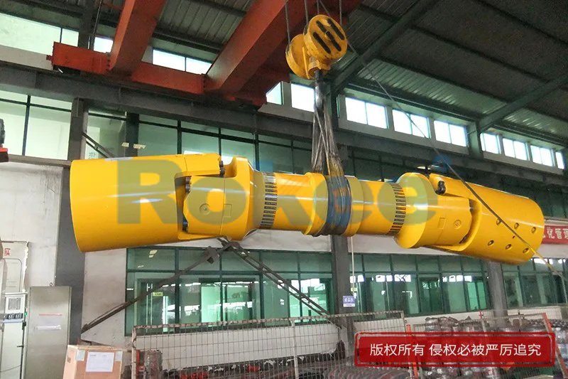


The universal coupling uses cross bearings to connect the flanges at both ends, which can transmit torque that is not on the same axis. The diagonal compensation can reach more than 25°, and the spline connection can compensate for the axial displacement in a large distance. With high carrying capacity and excellent transmission efficiency, universal coupling is widely used in modern industrial fields.
Universal Coupling Products
-
![ROWS-BH Cardan Shaft,Universal Couplings Size Chart]()
ROWS-BH Cardan Shaft
View More -
![ROWL-BH Cardan Shaft,Universal Couplings Size Chart]()
ROWL-BH Cardan Shaft
View More -
![ROWM-BH Cardan Shaft,Universal Couplings Size Chart]()
ROWM-BH Cardan Shaft
View More -
![ROWH-BH Cardan Shaft,Universal Couplings Size Chart]()
ROWH-BH Cardan Shaft
View More -
![ROWS-WD Cardan Shaft,Universal Couplings Size Chart]()
ROWS-WD Cardan Shaft
View More -
![ROWM-WD Cardan Shaft,Universal Couplings Size Chart]()
ROWM-WD Cardan Shaft
View More -
![ROWH-WD Cardan Shaft,Universal Couplings Size Chart]()
ROWH-WD Cardan Shaft
View More -
![ROWL-WD Cardan Shaft,Universal Couplings Size Chart]()
ROWL-WD Cardan Shaft
View More -
![ROWM-WH Cardan Shaft,Universal Couplings Size Chart]()
ROWM-WH Cardan Shaft
View More -
![ROWH-WH Cardan Shaft,Universal Couplings Size Chart]()
ROWH-WH Cardan Shaft
View More -
![ROWL-WH Cardan Shaft,Universal Couplings Size Chart]()
ROWL-WH Cardan Shaft
View More -
![ROWS-WH Cardan Shaft,Universal Couplings Size Chart]()
ROWS-WH Cardan Shaft
View More -
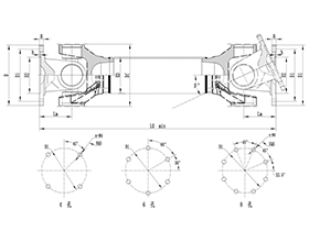
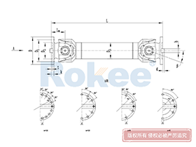
![SWC-BH Universal Coupling,Universal Couplings Size Chart]()
SWC-BH Universal Coupling
standard telescopic welded
View More -
![SWC-CH Uuniversal Coupling,Universal Couplings Size Chart]()
SWC-CH Uuniversal Coupling
Long Telescopic Welded
View More -
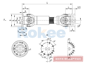
![SWC-DH Universal Coupling,Universal Couplings Size Chart]()
SWC-DH Universal Coupling
Short Telescopic Welded
View More -
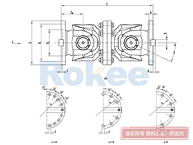
![SWC-WD Universal Coupling,Universal Couplings Size Chart]()
SWC-WD Universal Coupling
Non-telescopic Short
View More -
![SWC-WH Universal Coupling,Universal Couplings Size Chart]()
SWC-WH Universal Coupling
Non-telescopic Welded
View More -
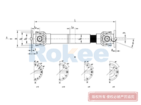
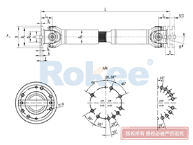
![SWP-A Universal Coupling,Universal Couplings Size Chart]()
SWP-A Universal Coupling
Long Type, Telescopic
View More -
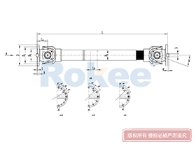
![SWP-B Universal Coupling,Universal Couplings Size Chart]()
SWP-B Universal Coupling
Short Type, Telescopic
View More -
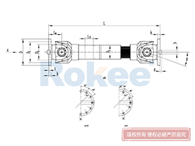
![SWP-C Universal Coupling,Universal Couplings Size Chart]()
SWP-C Universal Coupling
Short Type, Non-telescopic
View More -
![SWP-D Universal Coupling,Universal Couplings Size Chart]()
SWP-D Universal Coupling
Long Type, Non-elescopic
View More

In the intricate web of mechanical power transmission systems, universal couplings stand as indispensable components that bridge misaligned shafts, transfer torque efficiently, and maintain operational stability across a vast array of industrial applications. At the heart of selecting, installing, and maintaining these critical components lies the universal couplings size chart—a structured, data-driven reference tool that distills complex dimensional specifications into clear, actionable information for engineers, technicians, and maintenance professionals. Far more than a simple list of measurements, this chart serves as a foundational guide that aligns component dimensions with real-world operational demands, ensuring that every universal coupling chosen fits seamlessly into its intended system, performs reliably under varying loads, and withstands the rigors of continuous mechanical operation. Without a comprehensive understanding of the size chart and its nuanced details, even the most robust universal coupling risks premature failure, system inefficiency, or costly downtime, making it essential to delve into the purpose, structure, and practical application of this vital technical resource.
To grasp the full significance of a universal couplings size chart, it is first necessary to understand the core functional traits of universal couplings themselves. These components are engineered to accommodate angular, parallel, and axial misalignment between rotating shafts, a common challenge in machinery where perfect shaft alignment is rarely achievable due to manufacturing tolerances, thermal expansion, or operational wear. Unlike rigid couplings that demand precise alignment and transmit torque without flexibility, universal couplings offer controlled flexibility while preserving power transfer integrity, making them suitable for everything from light-duty precision equipment to heavy-duty industrial machinery. Each design variation of universal coupling—whether single-joint, double-joint, telescopic, or fixed-length—relies on standardized dimensional parameters to ensure compatibility with shaft sizes, mounting spaces, and torque requirements, and it is these parameters that form the backbone of every reliable size chart. The chart eliminates guesswork by consolidating all critical physical measurements in one place, allowing users to cross-reference specifications quickly and avoid mismatches that could compromise entire mechanical assemblies.
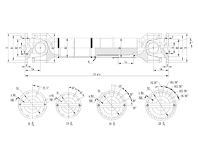
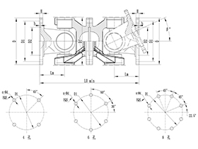
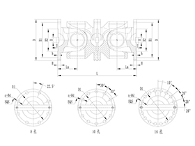
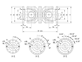
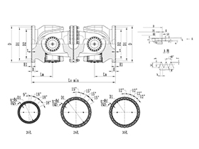
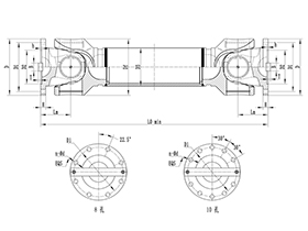
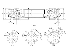
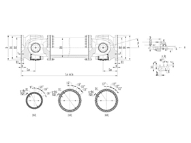
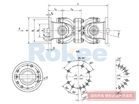
A well-constructed universal couplings size chart is organized around a set of consistent, universally recognized dimensional metrics that define the physical profile and functional capacity of each coupling variant. While specific layouts may vary slightly based on the type of universal coupling, the core dimensions included remain consistent across all credible charts, providing a standardized framework for comparison and selection. Key dimensional data typically featured includes bore diameter, overall length, outer diameter of the coupling body, length of the hub, distance between joint centers, and maximum angular misalignment capacity, alongside torque ratings that correlate directly to size. Bore diameter, one of the most pivotal measurements, denotes the inner diameter of the coupling hub that mates with the shaft, and it is available in a range of standard increments to fit common shaft sizes across industrial machinery. This measurement must align precisely with the shaft diameter to ensure a secure, slip-resistant connection, whether the coupling is secured via set screws, keyways, or clamping mechanisms—details that are often cross-referenced with bore size in the chart to enhance practical utility.
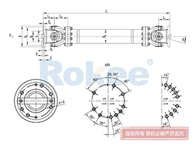
Overall length is another cornerstone measurement featured prominently in the size chart, as it dictates whether the coupling will fit within the available spatial constraints of a machine assembly. In compact equipment with limited clearance between shafts, a shorter overall length is non-negotiable, while heavy-duty industrial systems with greater shaft separation may require longer couplings to bridge the gap effectively. The outer diameter of the coupling body is equally critical, as it impacts not only fit within tight spaces but also the coupling’s moment of inertia and load-bearing capabilities; larger outer diameters generally correlate with higher torque capacity, making this dimension a key indicator of the coupling’s suitability for heavy-load applications. The length of the hub, meanwhile, influences the strength of the shaft-coupling connection, with longer hubs providing greater contact area and enhanced stability under high torque or vibrational stress. Each of these dimensions is presented in a logical, easy-to-follow format in the size chart, often grouped by coupling model or size series, allowing users to scan and compare multiple variants at a glance without sifting through disjointed technical data.
Beyond basic physical dimensions, the universal couplings size chart integrates critical operational parameters that tie size to performance, creating a holistic reference that bridges design and real-world use. These parameters include maximum allowable torque, rotational speed limits, and angular misalignment range, all of which are directly linked to the coupling’s physical size and structural design. Smaller, compact universal couplings, typically featured in the lower ranges of the size chart, are optimized for light-duty, high-speed applications such as precision instrumentation, small conveyor systems, or automotive auxiliary components, where minimal space usage and smooth torque transfer take priority. These smaller variants feature narrower bore diameters, shorter overall lengths, and lower torque capacities, tailored to the modest power requirements of lightweight machinery. In contrast, larger size couplings, found in the upper segments of the chart, boast robust construction, wider bores, and significantly higher torque ratings, engineered to handle the heavy loads and slower speeds characteristic of heavy industry—including manufacturing equipment, mining machinery, marine propulsion systems, and large-scale material handling units. The chart clearly maps these size-performance relationships, enabling users to match not just physical dimensions but also operational capabilities to their specific system needs.
One of the most valuable functions of the universal couplings size chart is its role in standardization and interoperability across mechanical systems. In an era where industrial machinery often incorporates components from multiple manufacturers, standardized size charts ensure that universal couplings are interchangeable regardless of production source, as long as they adhere to common dimensional norms. This standardization streamlines maintenance and replacement processes, as technicians can reference the size chart to source a compatible replacement coupling without needing proprietary specifications from the original equipment manufacturer. The chart also supports custom adaptation, as it highlights common dimensional thresholds and increments, allowing engineers to identify off-the-shelf couplings that can be modified slightly to fit unique shaft sizes or mounting configurations, rather than relying on fully custom-designed components that add time and complexity to projects. This balance of standardization and flexibility makes the size chart an invaluable tool for both new machinery design and retrofitting existing systems, ensuring that universal couplings can integrate smoothly into diverse mechanical setups.
Navigating a universal couplings size chart effectively requires a methodical approach that prioritizes system requirements over arbitrary size selection, and understanding this process is key to leveraging the chart’s full potential. The first step in using the chart is to compile precise measurements of the shafts the coupling will connect, including shaft diameter, shaft separation distance, and the degree of misalignment present—angular, parallel, or axial. These baseline measurements serve as the primary filter when scanning the chart, narrowing down the pool of suitable couplings to those with matching bore diameters and overall lengths that fit the available space. Next, users must assess the operational loads and speeds of the system, cross-referencing the torque and speed ratings in the chart with the actual power transmission demands of the machinery. It is crucial to select a coupling size that not only fits physically but also has a torque capacity that exceeds the system’s peak operating load, providing a safety buffer against sudden spikes in stress, wear over time, or unexpected operational strain. Skipping this step and choosing a coupling based solely on physical dimensions can lead to overloading, premature wear, or catastrophic failure during operation, even if the fit appears perfect.
Misalignment capacity, another detail tied to size in the chart, is a factor that is often overlooked but critical for long-term performance. Universal couplings vary in their ability to accommodate shaft misalignment based on their size and design, with larger, heavy-duty couplings typically offering greater misalignment tolerance to handle the substantial shifts common in heavy industrial equipment. Smaller precision couplings, by contrast, have more limited misalignment ranges, designed to correct minor alignment issues without introducing excessive vibration or backlash. The size chart clearly delineates these misalignment limits for each variant, allowing users to select a size that aligns with the specific misalignment challenges of their system. For applications with significant multi-directional misalignment, double-joint universal couplings, whose size specifications are also detailed in the chart, offer enhanced flexibility compared to single-joint variants, making the chart a vital resource for choosing not just the right size but also the right design configuration for misalignment management.
The practical application of the universal couplings size chart extends far beyond initial component selection, playing a vital role in ongoing maintenance, troubleshooting, and system optimization throughout the lifecycle of mechanical equipment. Over time, universal couplings experience wear from friction, torque stress, and environmental factors, leading to changes in dimensional integrity or performance that can disrupt system operation. When wear or damage occurs, maintenance teams can use the size chart to quickly identify the exact replacement part, minimizing equipment downtime by ensuring a precise, compatible fit without trial and error. The chart also aids in troubleshooting performance issues such as vibration, noise, or inconsistent torque transfer—if a coupling is operating outside its rated size parameters or is mismatched to the shaft dimensions, the chart can highlight the discrepancy and guide teams toward a correctly sized replacement. Additionally, when upgrading or modifying machinery to handle higher loads or faster speeds, engineers can reference the chart to scale up coupling size proportionally, ensuring that the component upgrades align with enhanced system demands and maintaining overall mechanical balance.
Environmental factors, while not direct dimensional measurements, are indirectly addressed through the size chart, as coupling size often correlates with durability and resistance to harsh operating conditions. Larger, heavy-duty universal couplings, with their robust structural dimensions outlined in the chart, are built to withstand exposure to dust, moisture, temperature extremes, and chemical contaminants commonly found in industrial environments. Their increased material mass and reinforced construction, reflected in their larger dimensional profiles, provide greater resistance to corrosion, impact, and fatigue compared to smaller, more delicate variants. For applications in harsh settings, the size chart helps users prioritize larger, sturdier coupling sizes that offer enhanced longevity, even if spatial constraints are tight, balancing fit with durability to reduce frequent replacement needs. In cleaner, controlled environments such as laboratory equipment or precision manufacturing tools, smaller-sized couplings from the chart are sufficient, as they deliver the required precision without the need for heavy-duty environmental resistance.
It is important to recognize that while universal couplings size charts follow broad standardization, subtle variations in dimensional tolerances may exist between different design types, and understanding these nuances is key to accurate selection. For example, telescopic universal couplings, which feature adjustable length to accommodate axial movement, have size chart entries that include both minimum and maximum length specifications, distinguishing them from fixed-length couplings with a single overall length measurement. The chart clearly differentiates these design-specific dimensions, ensuring that users do not confuse telescopic and fixed-length variants when making selections. Similarly, couplings designed for keyed shafts have hub dimensions tailored to accommodate keyways, which are noted alongside standard bore sizes in the chart, while keyless clamping-style couplings feature slightly different hub profiles to facilitate secure shaft clamping. These subtle details, meticulously documented in the size chart, prevent costly selection errors and ensure that the coupling integrates seamlessly with the shaft’s mounting mechanism.
As mechanical engineering and industrial technology continue to evolve, the universal couplings size chart remains a timeless, essential tool, adapting to incorporate new design innovations and emerging industry needs while retaining its core purpose of providing clear, reliable dimensional guidance. Modern iterations of the chart may include additional metrics such as weight specifications, material compatibility notes, and backlash tolerances, all tied to size, to further enhance its practical value for contemporary machinery design. Weight, for instance, is a critical consideration in mobile equipment or weight-sensitive assemblies, and the chart links size to weight, allowing engineers to balance load-bearing capacity with overall equipment weight. Backlash, the small amount of movement between coupling components, is also sizedependent, with larger couplings typically having minimal backlash for heavy-load stability, and the chart quantifies this trait to support precision-driven applications.
In summary, the universal couplings size chart is far more than a technical reference document—it is a cornerstone of efficient, reliable mechanical power transmission system design, installation, and maintenance. It distills the complex relationship between physical dimensions, operational performance, and application suitability into a accessible format, empowering users to make informed decisions that optimize system functionality, extend component lifespan, and reduce operational risks. From small-scale precision machinery to large industrial heavy equipment, the size chart ensures that universal couplings are matched perfectly to their intended use, balancing fit, performance, and durability in every application. By mastering the information presented in the chart and applying it methodically to system design and maintenance, engineering and maintenance professionals can unlock the full potential of universal couplings, ensuring smooth, consistent power transmission and minimizing disruptions in even the most demanding operational environments. Investing time in understanding the nuances of the size chart is not just a best practice—it is a critical step in building and maintaining mechanical systems that operate efficiently, reliably, and safely over the long term.
« Universal Couplings Size Chart » Update Date: 2026/3/7
URL: http:/en/blog/universal-couplings-size-chart.html
Tags: Universal Coupling Joint , Universal Coupling Shaft , Universal Couplings , sandwich panel machine