Universal Cross Joint Coupling Size Chart
Rokee® is a well-known high-quality universal cross joint coupling supplier from china, learn more about universal cross joint coupling size chart, pls contact Rokee technology. Rokee has been established in China since 1999, over the years, with excellent quality, we have been continuously providing many universal cross joint coupling products of various categories and uses complying with multiple standards and a full range of services, from the universal cross joint coupling selection to final installation and operation, for the industry fields of ferrous metallurgy, nuclear power, gas turbine, wind power, ropeway construction, lifting transportation, general equipment, etc.
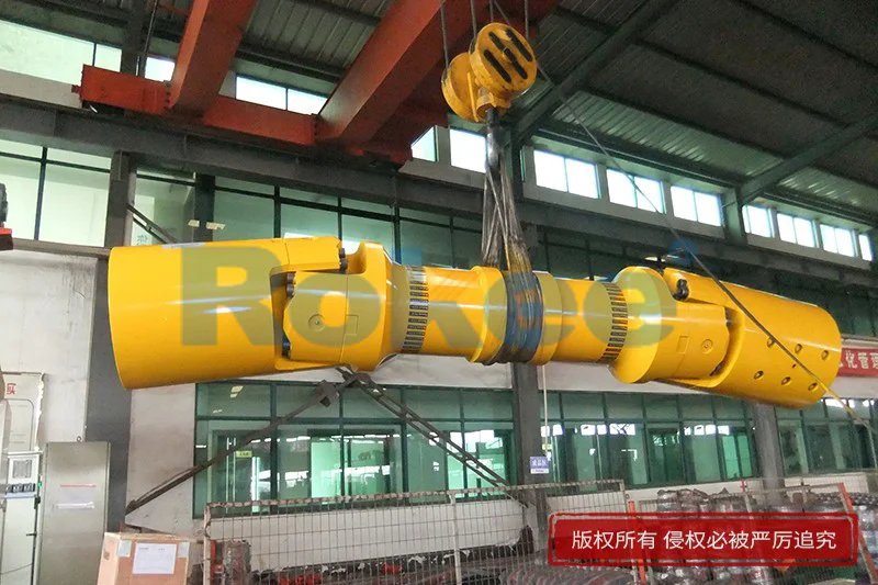


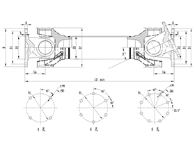
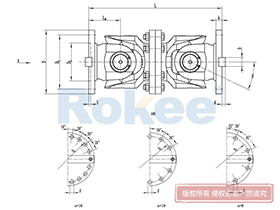
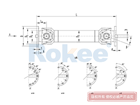
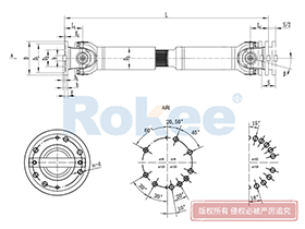
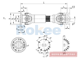
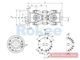
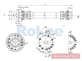
The universal cross joint coupling uses cross bearings to connect the flanges at both ends, which can transmit torque that is not on the same axis. The diagonal compensation can reach more than 25°, and the spline connection can compensate for the axial displacement in a large distance. With high carrying capacity and excellent transmission efficiency, universal cross joint coupling is widely used in modern industrial fields.
Universal Cross Joint Coupling Products
-
![ROWS-BH Cardan Shaft,Universal Cross Joint Coupling Size Chart]()
ROWS-BH Cardan Shaft
View More -
![ROWL-BH Cardan Shaft,Universal Cross Joint Coupling Size Chart]()
ROWL-BH Cardan Shaft
View More -
![ROWM-BH Cardan Shaft,Universal Cross Joint Coupling Size Chart]()
ROWM-BH Cardan Shaft
View More -
![ROWH-BH Cardan Shaft,Universal Cross Joint Coupling Size Chart]()
ROWH-BH Cardan Shaft
View More -
![ROWS-WD Cardan Shaft,Universal Cross Joint Coupling Size Chart]()
ROWS-WD Cardan Shaft
View More -
![ROWM-WD Cardan Shaft,Universal Cross Joint Coupling Size Chart]()
ROWM-WD Cardan Shaft
View More -
![ROWH-WD Cardan Shaft,Universal Cross Joint Coupling Size Chart]()
ROWH-WD Cardan Shaft
View More -
![ROWL-WD Cardan Shaft,Universal Cross Joint Coupling Size Chart]()
ROWL-WD Cardan Shaft
View More -
![ROWM-WH Cardan Shaft,Universal Cross Joint Coupling Size Chart]()
ROWM-WH Cardan Shaft
View More -
![ROWH-WH Cardan Shaft,Universal Cross Joint Coupling Size Chart]()
ROWH-WH Cardan Shaft
View More -
![ROWL-WH Cardan Shaft,Universal Cross Joint Coupling Size Chart]()
ROWL-WH Cardan Shaft
View More -
![ROWS-WH Cardan Shaft,Universal Cross Joint Coupling Size Chart]()
ROWS-WH Cardan Shaft
View More -
![SWC-BH Universal Coupling,Universal Cross Joint Coupling Size Chart]()
SWC-BH Universal Coupling
standard telescopic welded
View More -
![SWC-CH Uuniversal Coupling,Universal Cross Joint Coupling Size Chart]()
SWC-CH Uuniversal Coupling
Long Telescopic Welded
View More -
![SWC-DH Universal Coupling,Universal Cross Joint Coupling Size Chart]()
SWC-DH Universal Coupling
Short Telescopic Welded
View More -
![SWC-WD Universal Coupling,Universal Cross Joint Coupling Size Chart]()
SWC-WD Universal Coupling
Non-telescopic Short
View More -
![SWC-WH Universal Coupling,Universal Cross Joint Coupling Size Chart]()
SWC-WH Universal Coupling
Non-telescopic Welded
View More -
![SWP-A Universal Coupling,Universal Cross Joint Coupling Size Chart]()
SWP-A Universal Coupling
Long Type, Telescopic
View More -
![SWP-B Universal Coupling,Universal Cross Joint Coupling Size Chart]()
SWP-B Universal Coupling
Short Type, Telescopic
View More -
![SWP-C Universal Coupling,Universal Cross Joint Coupling Size Chart]()
SWP-C Universal Coupling
Short Type, Non-telescopic
View More -
![SWP-D Universal Coupling,Universal Cross Joint Coupling Size Chart]()
SWP-D Universal Coupling
Long Type, Non-elescopic
View More

In the realm of mechanical power transmission, the universal cross joint coupling stands as a fundamental component that bridges misaligned shafts, transfers torque efficiently, and sustains the operational stability of diverse machinery systems. A comprehensive and accurate size chart for these couplings is not merely a reference document but a critical tool for engineers, technicians, and procurement professionals, guiding precise selection, seamless installation, and long-term reliable performance. Every dimension outlined in the size chart is tailored to balance mechanical strength, angular compensation capacity, and compatibility with surrounding equipment, ensuring that the coupling can withstand operational stresses, adapt to shaft misalignments, and integrate flawlessly into transmission setups across light, medium, and heavy-duty applications. Understanding the nuances of the universal cross joint coupling size chart requires a deep dive into core dimensional parameters, their interrelationships, and the practical implications of size matching for real-world industrial operations.
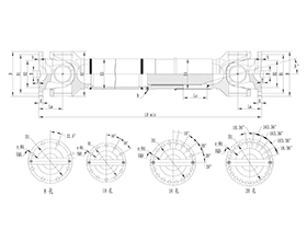
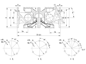
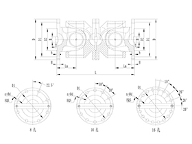
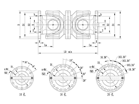
At the heart of the universal cross joint coupling size chart are several key dimensional metrics that define the product’s form, fit, and function, each playing a distinct role in determining its suitability for a specific application. The outer diameter of the cross bearing assembly is a primary specification, as it directly correlates with the coupling’s torque-bearing capability and overall structural robustness. Smaller outer diameters are typically engineered for light-duty scenarios with low torque loads and limited space constraints, such as small-scale automated machinery, precision testing equipment, and light automotive auxiliary systems. These compact sizes prioritize space efficiency and smooth rotational movement, delivering consistent power transfer without imposing excessive weight or bulk on the transmission system. In contrast, larger outer diameters are designed to handle substantial torque outputs and heavy operational impacts, making them ideal for heavy industrial machinery, large-scale construction equipment, and heavy-duty transportation systems where load-bearing capacity is non-negotiable. The size chart clearly delineates these gradations, allowing users to match the cross bearing outer diameter to the peak torque requirements of their equipment, avoiding under-sizing that leads to premature failure or over-sizing that wastes material and increases operational friction.
Another pivotal dimension featured in the size chart is the shaft bore diameter, which dictates the coupling’s compatibility with the drive and driven shafts it connects. This parameter is meticulously standardized to align with common shaft sizes across global mechanical design norms, covering a wide spectrum from miniature bores for precision instruments to large-diameter bores for heavy industrial drive shafts. The bore diameter must align precisely with the shaft diameter to ensure a tight, secure fit; even a minor mismatch can result in wobbling during rotation, power loss, accelerated wear on mating components, and potential mechanical breakdowns. The size chart not only lists nominal bore diameters but also includes tolerance ranges, keyway dimensions, and spline specifications where applicable, providing detailed data to support custom fitting and assembly. For applications involving non-standard shaft sizes, the dimensional data in the chart serves as a baseline for custom modifications, ensuring that the coupling can be adapted without compromising its core performance attributes. Additionally, the length of the coupling body, from end to end, is a critical spatial dimension outlined in the chart, accounting for installation clearances, axial movement limits, and integration with adjacent components such as gearboxes, motors, and driven machinery. This length parameter is carefully calibrated to balance angular deflection capacity and axial stability, preventing interference with nearby parts while enabling the coupling to accommodate the required degree of angular and parallel misalignment.
Beyond individual dimensional values, the universal cross joint coupling size chart organizes specifications into coherent size series, grouping couplings with similar proportional dimensions and performance characteristics to simplify the selection process. Each size series is curated to cater to a specific range of operational conditions, including rotational speed thresholds, misalignment compensation limits, and environmental operating temperatures. For instance, compact size series are optimized for high-speed, low-load applications where rotational balance and minimal vibration are paramount, such as textile manufacturing machinery, printing equipment, and precision CNC machine tools. These series feature streamlined dimensions, reduced rotational inertia, and tight tolerance controls to maintain smooth operation at elevated speeds, minimizing energy loss and heat generation. Mid-range size series strike a balance between load capacity and flexibility, serving as versatile solutions for general industrial machinery including conveyor systems, packaging equipment, and agricultural machinery. These couplings offer moderate torque ratings and angular misalignment compensation, adapting to the variable loads and moderate misalignments common in everyday industrial operations. Heavy-duty size series, meanwhile, feature reinforced dimensions, thicker structural walls, and enhanced bearing configurations to handle extreme torque, shock loads, and large angular misalignments, making them suitable for mining equipment, steel rolling mills, marine propulsion systems, and large-scale material handling machinery. The size chart clearly maps each series to its intended operational envelope, enabling users to narrow down options quickly based on their equipment’s speed, load, and misalignment requirements.
Angular misalignment capacity is a performance attribute closely tied to the dimensional specifications in the universal cross joint coupling size chart, and it is a defining feature that sets these couplings apart from rigid transmission components. The cross-shaped bearing design allows for angular deflection between the drive and driven shafts, and the degree of permissible misalignment is directly influenced by key dimensions such as the length of the yoke arms, the diameter of the cross trunnions, and the overall profile of the coupling body. The size chart quantifies this angular compensation range for each size variant, typically spanning from a few degrees for precision-focused small couplings to over twenty degrees for heavy-duty, flexible variants. This data is indispensable for applications where shaft misalignment is unavoidable, such as mobile machinery with dynamic movement, industrial equipment subject to thermal expansion, and systems with cumulative assembly tolerances. By cross-referencing the angular misalignment data with dimensional specifications, users can select a coupling size that not only fits physically but also accommodates the full range of misalignment encountered during operation, preventing excessive stress on shafts, bearings, and other transmission components. Proper size selection in this regard also extends the service life of the coupling, as it reduces fatigue wear caused by forced alignment and uneven load distribution.
Material compatibility and structural integrity are also implicitly reflected in the universal cross joint coupling size chart, as dimensional proportions are engineered to complement the mechanical properties of common coupling materials. Most standard universal cross joint couplings are constructed from high-strength alloy steel, chosen for its excellent tensile strength, wear resistance, and fatigue durability, while specialized variants may use corrosion-resistant alloys for harsh environments. The size chart’s dimensions are optimized to leverage these material properties: smaller couplings feature refined, precision-machined dimensions to maintain strength in compact form factors, while larger couplings incorporate reinforced sections and optimized wall thicknesses to distribute heavy loads evenly across the structure. For example, the cross trunnion diameter and yoke thickness are scaled proportionally with overall coupling size, ensuring that stress is dispersed uniformly during torque transmission and rotational movement. This dimensional optimization eliminates weak points in the structure, reducing the risk of cracking, bending, or bearing failure under continuous operation. The size chart also accounts for machining tolerances and assembly clearances, ensuring that even with variations in material hardness and manufacturing precision, each coupling size maintains consistent performance and interchangeability across production batches.
Practical application of the universal cross joint coupling size chart extends beyond initial selection, playing a vital role in installation, maintenance, and replacement workflows. During installation, the dimensional data ensures that the coupling is mounted correctly, with proper alignment, adequate clearance, and secure fastening to the shafts. Technicians can reference bore diameters, keyway sizes, and overall length to prepare shafts and mating components, streamlining the assembly process and reducing the risk of installation errors that compromise performance. For routine maintenance, the size chart helps identify wear patterns and component degradation by comparing actual measured dimensions to the nominal specifications in the chart. Changes in critical dimensions such as bearing play, yoke gap, or overall length can signal excessive wear, prompting timely maintenance or replacement before a catastrophic failure occurs. When replacing a worn or damaged coupling, the size chart serves as a definitive reference for sourcing an identical or equivalent replacement, ensuring compatibility with existing shafts and equipment without the need for costly modifications. This seamless replacement capability minimizes equipment downtime, a critical consideration in industrial settings where operational continuity directly impacts productivity and efficiency.
The versatility of universal cross joint couplings, as reflected in their comprehensive size chart, makes them indispensable across a vast array of industries, each with unique operational demands and spatial constraints. In the automotive industry, compact-sized couplings are used in drive trains, steering systems, and auxiliary components, where space is limited and smooth power delivery is essential for vehicle handling and performance. These small, precision-sized couplings adapt to the dynamic misalignments caused by suspension movement and engine vibration, ensuring consistent power transfer to wheels and auxiliary systems. In agricultural machinery, mid-range couplings handle the variable loads and rough operating conditions of farm equipment such as tractors, harvesters, and irrigation systems, with size specifications tailored to withstand dust, debris, and intermittent heavy loads. The construction sector relies on heavy-duty sized couplings for cranes, excavators, and concrete mixers, where large torque capacities and robust dimensional designs are needed to endure heavy lifting, constant movement, and harsh job site conditions. In industrial manufacturing, from food processing lines to heavy machinery assembly lines, the full spectrum of coupling sizes caters to diverse equipment needs: small precision sizes for delicate processing machinery, mid-range sizes for automated assembly lines, and large heavy-duty sizes for metalworking and fabrication equipment. Even in marine and aerospace applications, specialized size variants with corrosion-resistant dimensions and high-precision tolerances ensure reliable performance in challenging environments, highlighting the adaptability enabled by a well-structured size chart.
As mechanical engineering and industrial technology continue to evolve, the universal cross joint coupling size chart remains a dynamic document, updated regularly to incorporate advancements in design, materials, and manufacturing processes. Modern size charts integrate digital compatibility features, allowing for seamless integration with computer-aided design (CAD) software, enabling engineers to import dimensional data directly into equipment models for virtual testing and alignment checks. This digital integration enhances the accuracy of size selection, reduces design lead times, and minimizes the risk of compatibility issues in complex transmission systems. Additionally, ongoing refinements to dimensional specifications based on field performance data and material science innovations ensure that the size chart remains aligned with the latest industry demands for higher efficiency, greater durability, and more sustainable design. Whether for traditional mechanical setups or cutting-edge automated systems, the size chart continues to serve as a cornerstone of effective coupling selection, bridging the gap between theoretical design and practical operational needs.
In summary, the universal cross joint coupling size chart is an essential resource that encapsulates decades of engineering expertise, practical testing, and industrial application knowledge. Every dimension, tolerance, and specification within the chart is purposefully designed to empower users to make informed decisions, optimize equipment performance, and ensure the longevity of mechanical transmission systems. By understanding the significance of each dimensional parameter, the logic behind size series categorization, and the practical implications of size matching, professionals can harness the full potential of universal cross joint couplings across countless applications. From small-scale precision machinery to heavy industrial giants, the right size selection, guided by a comprehensive and reliable size chart, is the foundation of efficient power transmission, minimal downtime, and sustained operational excellence. As machinery becomes more advanced and operational demands more rigorous, the role of the universal cross joint coupling size chart will only grow in importance, remaining a vital tool for engineering success in the global mechanical industry.
Investing time in studying and applying the data from the universal cross joint coupling size chart yields tangible benefits: reduced maintenance costs, extended equipment service life, enhanced operational safety, and improved overall system efficiency. It eliminates guesswork from coupling selection, ensuring that each component is perfectly matched to its intended application, and provides a standardized framework for communication between design, production, and maintenance teams. In a world where mechanical reliability is paramount, the universal cross joint coupling size chart stands as a testament to the importance of precision engineering and meticulous specification, driving progress and performance in every sector that relies on robust power transmission solutions.
« Universal Cross Joint Coupling Size Chart » Update Date: 2026/3/7
URL: http:/en/blog/universal-cross-joint-coupling-size-chart.html
Tags: Universal Cross Joint Couplings , sandwich panel machine